#!/usr/bin/env python
# coding: utf-8
# [ ](https://drivetrainhub.com)
#
#
](https://drivetrainhub.com)
#
# © 2020 Drivetrain Hub LLC
# # Strength / Force Analysis
# ---
#
# **Authors**: [Tugan Eritenel](https://github.com/tugan1)
#
# **Description**: Calculation of gear forces in parallel axis spur and helical gears.
# ## Table of Contents
#
# 1. [Introduction](#Introduction)
# 1. [Nomenclature](#Nomenclature)
# 1. [Gear Forces](#Gear-Forces)
# 1. [Example](#Example-1)
# 1. [References](#References)
# #### Notebook imports and settings
# In[1]:
import math
from math import pi
from IPython import display
from IPython.core.display import HTML
# ## Introduction
#
# The forces on gears are needed for gear design. In particular, root stress and contact stress depend on the gear tooth forces. Root stress and contact stress determine the size of the gears, and they are discussed in another notebook.
#
# Design of supporting shafts and bearings also require gear tooth forces. Spur gears only generate forces in the gear plane, however helical gears generate an axial force component therefore need to be supported axially as well. Tangential and radial forces in the gear plane cause bending moments on the supporing shafts. Axial force generates bending in the perpendicular plane. Considering these, the calculation of gear forces is important in design of shafts and bearings.
#
# 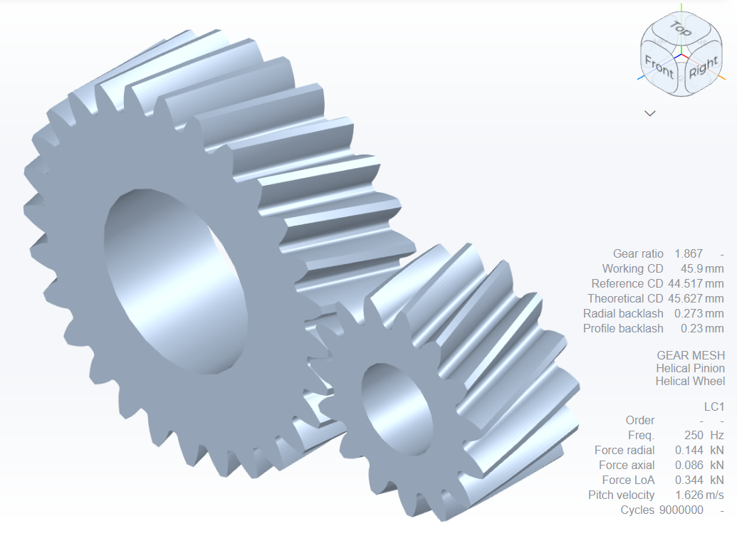 #
# Helical gear mesh modeled in Gears App
# ### Nomenclature
#
#
#
# | Symbol |
# Description |
#
#
# | $d_p$ |
# Pitch circle diameter |
#
#
# | $d_b$ |
# Base circle diameter |
#
#
# | $\alpha$ |
# Normal pressure angle |
#
#
# | $\alpha_t$ |
# Transverse pressure angle |
#
#
# | $\alpha_w$ |
# Working normal pressure angle |
#
#
# | $\alpha_{tw}$ |
# Working transverse pressure angle |
#
#
# | $\beta$ |
# Helix angle at pitch circle |
#
#
# | $a$ |
# Operating center distance |
#
#
# | $T$ |
# Applied torque on gear |
#
#
# | $F_N$ |
# Normal force |
#
#
# | $F_t$ |
# Tangential (circumferential) force |
#
#
# | $F_a$ |
# Axial force |
#
#
# | $F_r$ |
# Radial force |
#
#
# ## Gear Forces
#
# Force between mating gears develops normal to the contacting surfaces. This normal force, $F_N$, can be decomposed into axial force $F_a$, radial force $F_r$, and tangential force $F_t$. Figure 1 illustrates the tangential and radial forces in spur gears.
#
# 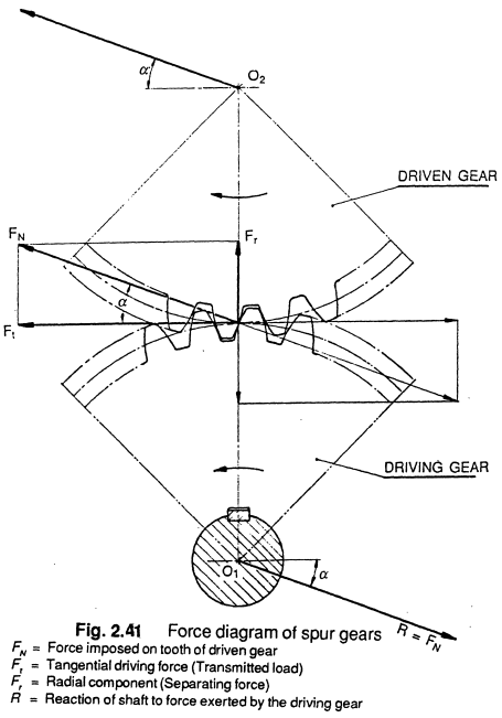 #
# Figure 1. Forces on spur gears.
# Image credit: G. M. Maitra, Handbook of Gear Design
# An axial component of force exists in helical gears but not spur gears. Figure 2 illustrates the normal force and its decomposition in the axial and transverse planes in helical gears.
#
# 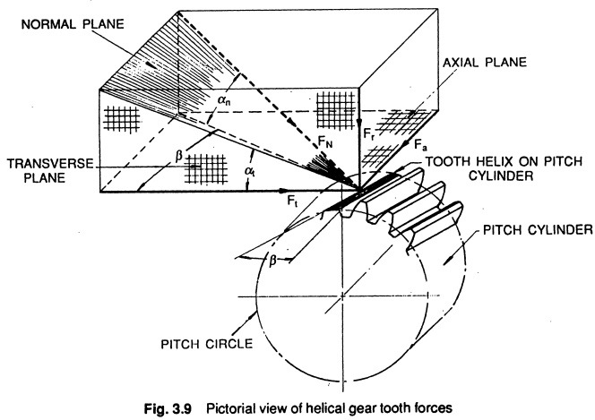 #
# Figure 2. Forces on helical gears.
# Image credit: G. M. Maitra, Handbook of Gear Design
# The normal force is distributed along the contact line, which moves as the gears rotate. Because of static equilibrium, the sum of this distributed force must equal the torque applied to the gear. Although the force is distributed, the operating pitch circle can be taken as an approximation to the average location for the point of contact.
#
# The tangential force, $F_t$, is tangent to the operating pitch circle in the transverse plane. The moment generated by the tangential force at pitch circle equals the applied torque. The tangential force is then given by,
#
# $$F_t = \frac{2T}{d_p}$$
#
# Considering the projection of the normal force in the transverse plane, the tangential force is one component; the other component is the radial force. The radial force can be calculated as,
#
# $$F_r = F_t \tan\alpha_{tw}$$
#
# Considering the axial plane, the axial force is one component of the force. The other component is the tangential force. Then, the axial force is found by,
#
# $$F_a = F_t \tan\beta$$
#
# Lastly, the normal force is the vector summation of these three components, with its magnitude calculated as,
#
# $$F_N = \sqrt{F_a^2 + F_r^2 + F_t^2}$$
#
#
Example | Gear Force Analysis
#
GIVEN
# - A gear pair, pinion-wheel, is in steady-state operation with static equilibrium. Geometry and operating conditions are as follows:
# - Number of pinion teeth is $z_p = 15$
# - Number of wheel teeth is $z_w = 45$
# - Normal module is $m_n = 2.5 \text{mm}$
# - Normal pressure angle is $\alpha = 20^\circ$
# - Helix angle is $\beta = 20^\circ$
# - Center distance is $a = 80 \text{mm}$
# - Applied torque on the pinion is $T = 100 \text{Nm}$
#
FIND
# Component of forces acting on the pinion.
#
SOLUTION
# See below.
#
# The working pitch diameter is $d_{w1} = 40 \text{mm}$, transverse working pressure angle is $\alpha_{tw} = 21.515^\circ$, and tangential force is calculated as $F_t = 2T / d_p$.
#
# In[3]:
# SOLUTION
# --------
d_w1 = 40
alpha_tw = 21.515
F_t = 2 * T / (d_w1 / 1000)
display.display(HTML('Tangential force, $F_{t}$ = ' + str(round(F_t,3)) + 'N
'))
#
# The radial and axial forces are calculated from the equations, $ F_r = F_t \tan\alpha_{tw}$, and $F_a = F_t \tan\beta$, respectively. The total normal force is then calculated from equation $F_N = \sqrt{F_a^2 + F_r^2 + F_t^2}$.
#
# In[4]:
# SOLUTION
# --------
F_r = F_t * math.tan(alpha_tw / 180 * pi)
F_a = F_t * math.tan(beta / 180 * pi)
F_N = math.sqrt(F_t**2 + F_r**2 + F_a**2)
display.display(HTML('Radial force, $F_{r}$ = ' + str(round(F_r,1)) + 'N
'))
display.display(HTML('Axial force, $F_{a}$ = ' + str(round(F_a,1)) + 'N
'))
display.display(HTML('Normal force, $F_{N}$ = ' + str(round(F_N,1)) + 'N
'))
#
# Lastly, the forces on the wheel must be equal and opposite to those calculated for the pinion. This is required to achieve static equilibrium. Also, it should that the pinion and wheel will need to be supported, e.g. with rolling element bearings, to react the radial, axial and tangential forces.
#
# ---
#
#
Model Gears
#
Gears App software will accurately model and analyze gear mesh forces, entirely in your
web browser.
#
#
Learn More
#
Notebook Series is free to learn and contribute knowledge about gears, such as geometry, manufacturing, strength, and more.
#
#
Edit Notebook
#
GitHub repos are used to publicly host our notebooks, allowing anyone to view and propose edits.
#